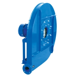
AAVA
Model
AAVA 500/P T2 1,1kW (std)
Kod
502405018

AAVA 500/P T2 1,1kW (std)

CECHY:
• Obudowa spawana, wykonana z blachy ze stali walcowanej. Obudowa pokryta farbą poliestrową (średnia odporność cieplna powłoki 180ºC).
• Wirnik wysokiej sprawności o pojedynczym wlocie powietrza z łopatkami wygiętymi do tyłu, wykonany z blachy ze stali walcowanej z powłoką epoksydową nakładaną proszkowo, odporny na temperaturę powyżej 300ºC. Wirnik wyważany dynamicznie.
• Możliwa zmiana figury wentylatora w modelach o wielkościach od 220 do 630. W modelach o wielkościach od 710 do 1000 orientacja ustalona.
• Standardowy asynchroniczny silnik klatkowy, stopień ochrony IP 55, izolacja klasy F. Standardowe napięcia zasilania: 230V, 50 Hz dla silników jednofazowych, 230/400V, 50 Hz dla silników trójfazowych do 4 kW i 400/690V, 50 Hz dla silników większych mocy.
• Standardowa figura - LG270.
 
ZASTOSOWANIE:
Zaprojektowane do montażu kanałowego. Odpowiednie dla:
• Instalacji przemysłowych, wywiewania i nawiewania powietrza.
• Chłodzenia maszyn i części.
• Transportu czystego powietrza.
• Usuwania powietrza za filtrami, separatorami i cyklonami.
• Transportu pneumatycznego.
• Maksymalnej temperatury roboczej: 130ºC dla przepływającego powietrza, otoczenia 60ºC.
 
DOSTĘPNE NA ŻYCZENIE:
• Wentylatory 60 Hz i specjalne napięcia zasilania.
• Wentylatory dwubiegowe.
• Wentylatory przeciwwybuchowe z certyfikowanymi silnikami ATEX.
• Wentylatory dla temperatur roboczych powietrza do 250ºC (zespół chłodzenia).
• Wentylatory w orientacji: RD0, RD45, RD90, RD135, RD180, RD225, RD270, RD315, LG0, LG45, LG90, LG135, LG180. LG225, LG315.
• Wentylatory w wykonaniu z blachy ze stali ocynkowanej na gorąco lub ze stali nierdzewnej.

Wentylator

Maksymalny przepływ
330 m³/h
Waga
51 Kg

Silnik

Moc
1,1 kW
Silnik obr./min
2800
I max. 230 V
4,05
I max. 400 V
2,33
Rozmiar
80
Waga
16 Kg
Wydajność
82.7 %
FP
0.85
AAVA 500/P T2 1,1kW (std)
Loading...
Punkt projektowy
Loading...
Punkt obsługi
Loading...
Punkt alternatywny

AAVA 500/P T2 1,1kW (std)

Dimensions scheme
A B D E F G H I L M N N1xØ1 N2xØ2 O Ø3 Øa Øb Øc Ød Ød1 Ød2 P
34 335 350 705 300 31 355 121 45 211 45 4x8,5 Nº8 M6x20 203 10 54 84 104 145 182 215 225

AAVA 500/P T2 1,1kW (std)

Electrical scheme

AAVA 500/P T2 1,1kW

Model
INT 25 3P A
Code
INT253PA
Information
WYŁĄCZNIK BEZPIECZEŃŚTWA
WYŁĄCZNIK BEZPIECZEŃSTWA Wyłącznik bezpieczeństwa start-stop. Wykorzystywany do zatrzymywania wentylatorów przed przystąpieniem do wykonywania prac serwisowych lub konserwacyjnych. Zgodność z wymogami normy IEC 947-3. Stopień ochrony IP65.
Model
BA-400 15/16
Code
960002067
Information
ZŁĄCZE PRZECIWDRGANIOWE 400ºC/2H

KOŁNIERZ ELASTYCZNY O ODPORNOŚCI TEMPERATUROWEJ 400ºC/2H Kołnierz elastyczny dla uniknięcia zjawiska przenoszenia się wibracji do instalacji.

Model
JE 45
Code
A-300719201
Information
ZŁĄCZE ELASTYCZNE

Elastyczne złącze do zanitowania między wentylatorem i kanałem. Pomaga zapobiegać przeniesieniu wibracji. Wymiary: Kołnierze metalowe: 45 mm; kołnierz elastyczny: 60 mm.

Model
AC 150
Code
960003204
Information
KOŁNIERZ PRZYŁĄCZENIOWY
KOŁNIERZ NA WLOCIE I WYLOCIE POWIETRZA Kołnierz przyłączeniowy do montażu na wlocie i wylocie wentylatorów osiowych.
Model
RA 145x8
Code
510001400
Information
OSŁONA WLOTU
SIATKA OCHRONNA NA WLOCIE Siatka ochronna na wlocie. Specjalnie zaprojektowana dla ochrony przed kontaktem z obracającym się wirnikiem i przedostawaniem się przedmiotów. Wykonanie ze spawanego drutu metalowego.
Model
RI 54x4
Code
510100500
Information
OSŁONA WYLOTU
SIATKA OCHRONNA NA WYLOCIE Siatka ochronna na wylocie. Specjalnie zaprojektowana dla ochrony przed kontaktem z obracającym się wirnikiem i przedostawaniem się przedmiotów. Wykonanie ze spawanego drutu metalowego.
Model
EI 54x4-54
Code
510200500
Information
KOŁNIERZ WYLOTU
KOŁNIERZ NA WYLOCIE POWIETRZA Kołnierz przyłączeniowy do montażu na wylocie wentylatorów odśrodkowych.
Model
FS 500
Code
*GH-FS500
Information
FRONTAL FEET SUPORT

Frontal feet support for medium ang high pressure fans

MB22/9-28/11 and MB31/12-45/18

Option frontal feet for models between 22/9 and 45/18

MBGR, MTGR*, MBRU, MTRU*, MBRM, MTRM*, MTRL*, MBCA, MTCA*, MBZM P/R and MTZM P/R*

Models of size 560 and above are supplied with a front support foot, for the other models the front support foot is optional.

AATZA*, AATVC*, AATVP*, AATVG/N* and AATVM*

Models of size 710 and above are supplied with a front support foot, for the other models the front support foot is optional.

AAZA, AAVC/N, AAVP/N, AAVG/N, AAVM, AAVA and AATVA*

Opcional frontal support in all models. For models until size 630 it can be supplied as an accessory, formodels of size 710 and above the frontal support is welded and it must be ordered with the fan (under request)

* For system 12 fans a special basefame is needed for installing the frontal support

Generic image, in some models the real foot may differ from the shown image

Model
SFC 230 I 4,2A *
Code
SFC230I004
Information
FREQUENCY SPEED CONTROLLER

MANUFACTURING FEATURES

• Specially designed for speed frequency control in ventilation applications.
• Ultra compact, simple operation and wide range of functions.

*Dial panel incorporated. Optional EMC filter.

Certifications: CE/UL/CSA/EN/GOST/CCC.

Protection index IP20.

The selection of SFC frequency drive speed controller must be made based on the maximum intensity absorbed by the fan to be regulated. The powers (kW) and the intensity for constant load refer to the normal duty (150% overload for 60 seconds). The intensity for quadratic load admits an overload of 110% during 60s.

SFC 230: Entrance 230V I, exit 230V III
SFC 400: Entrance 400V III, exit 400V III

EMC filter incorporated for models from 47A (included)

*Lineal load rated current

**Quadratic load rated current

Model
SFC 400 III 3,6A *
Code
SFC400III4
Information
FREQUENCY SPEED CONTROLLER

MANUFACTURING FEATURES

• Specially designed for speed frequency control in ventilation applications.
• Ultra compact, simple operation and wide range of functions.

*Dial panel incorporated. Optional EMC filter.

Certifications: CE/UL/CSA/EN/GOST/CCC.

Protection index IP20.

The selection of SFC frequency drive speed controller must be made based on the maximum intensity absorbed by the fan to be regulated. The powers (kW) and the intensity for constant load refer to the normal duty (150% overload for 60 seconds). The intensity for quadratic load admits an overload of 110% during 60s.

SFC 230: Entrance 230V I, exit 230V III
SFC 400: Entrance 400V III, exit 400V III

EMC filter incorporated for models from 47A (included)

*Lineal load rated current

**Quadratic load rated current

Model
AVR (GENERIC)
Code
Information
ANTI-VIBRATION RUBBER BLOCK

MANUFACTURING FEATURES

• Support of great radial and axial elasticity.
• These low-profile, compact and elastic supports control the three directions of movement with large deformations in the rubber.
• It consists of two parallel armour adhered to the bell-shaped rubber and by a base with handles.
• These supports with handles have a threaded hole in their upper frame and are easy to install and fix.
• The steel protection washer allows it to withstand overloads by increasing its rigidity and protects the rubber from dripping hydrocarbons.
• Elastomer type NR or high quality elastomer. Working temperatures between -40ºC and + 70º C.
• Taking into account the tolerances of hardness in the elastomers, the mechanical characteristics of these series may differ.
• Range of 6 sizes and 3 different hardnesses (45-60-75) to fit a load range between 2 Kg and 1300 Kg.
      1. Soft: hardness A 45
      2. Average: hardness B 60
      3. Hard: hardness C 75

APPLICATIONS

• Very appropriate in the elastic suspensions of machines that present vibrations of horizontal components.

Model
AVS (GENERIC)
Code
Information
ANTI-VIBRATION SPRING BLOCK

MANUFACTURING FEATURES

• Metal insulators designed to work with compression with 85% insulation according to the following arrows (travel in mm) and rpm:

Arrow (mm.)          r.p.m.
    20 mm          >600 r.p.m.
    30 mm          >500 r.p.m.

• Made of high quality elastic steel, with rectangular base and rubber mat to improve the grip. It treats of a resistant product and easy assembly, that avoids all type of vibrations of the fans to the structure of the premises.
• Operating temperature from -45 ° C to + 120 ° C.

APPLICATION

• To install under machines with rotating components, ventilation groups, fans, ventilation boxes, etc.

Model
AB (GENERIC)
Code
Information
ACOUSTIC CABINS FOR CENTRIFUGAL FANS

Structure made of extruded aluminum profiles available in different dimensions according to the panel to be installed and the fan volume. The profiles joining is made of polyamide corners, which gives them great strength and the possibility of disassembling the structure into pieces.

Panels can be made of a single sheet with inner insulation of 10 mm thick polyethylene foam, or 2 sheets (sandwich panel) with thicknesses of 25 mm or 50 mm, depending on the required attenuation degree.

The sheets of each panel can be galvanized steel, galvanized steel with coloured plastic coating or stainless steel.

The lower part is finished off with a structure / plinth for transport and handling, made of galvanized sheet or upn-80/100 joist, depending on the cabin dimensions and weight.

The air inlets and outlets of the cabin have anti-vibration tarpaulins coupled to mounted fans. These fans rest on a floating base with acoustic dampers.

RRP to consult.

AAVA 500/P T2 1,1kW (std)

Spare parts scheme
Kod Rodzina Nazwa Qty
2 T02405018 IMPELLER AAVA 500/P LG x1
3 505605000SP04 INLET CONE AAVA-AATVA 500/P x1
4 721001041 SILNIK 1,1KW T2 B5 230/400V x1